
Culverts are required where natural or manmade channels are crossed by roads or streets.

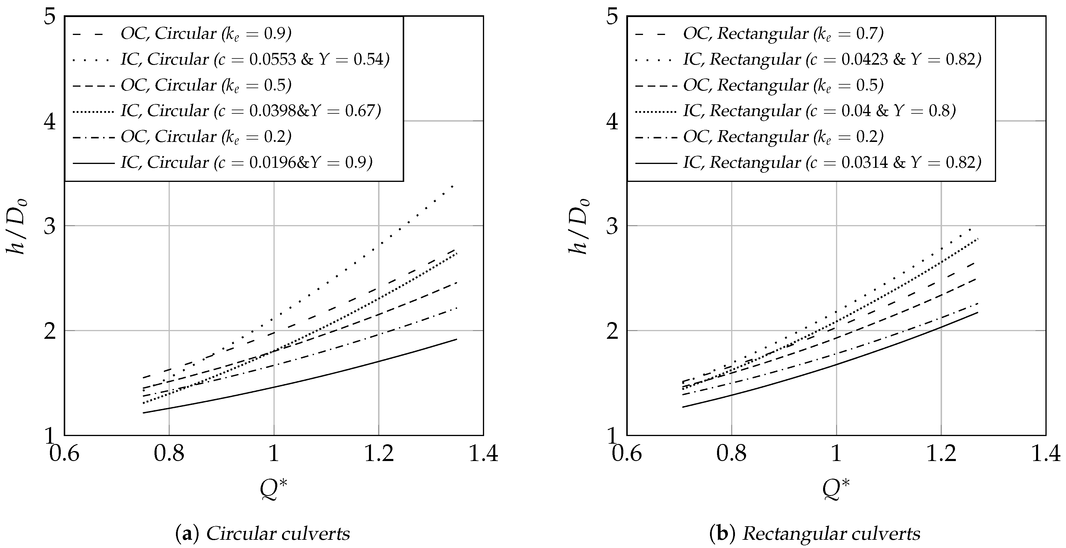
Culvert hydraulic calculations shall be performed using rating nomographs and/or culvert hydraulic analysis programs. The control condition which produces the greater energy loss for the design condition determines the appropriate control to use for the culvert design. When designing a culvert, the designer must evaluate both inlet and outlet control conditions for the given design constraints (e.g., discharge, headwater, tailwater, outlet velocity, etc.). Under outlet control, the flow through the culvert is controlled primarily by culvert slope, roughness, and tailwater elevation. Under inlet control, the flow through the culvert is controlled by the headwater on the culvert and the inlet geometry. Inlet and outlet control are the two basic types of flow in culverts. HDS-5 is the required method for design of culverts in Mesa County and in the City of Grand Junction and shall be used for all situations not covered in this chapter. The more commonly used nomographs from HDS-5 are provided in this chapter. These nomographs are the basis for the culvert design process. These data were used to develop culvert design aids, called nomographs.
#Box culvert flow rate calculator series
Research by the National Bureau of Standards sponsored and supported by the FHWA resulted in a series of reports providing a comprehensive analysis of culvert hydraulics under various flow conditions. The information and references necessary to design culverts according to the procedure given in this chapter can be found in the Federal Highway Administration (FHWA) Hydraulic Design of Highway Culverts, Hydraulic Design Series No.

The user is assumed to possess a basic knowledge of culvert hydraulics and is encouraged to review the technical literature on the subject. This chapter presents the general procedures for hydraulic design and evaluation of culverts. The hydraulic aspects of culvert and bridge design are covered in this chapter.Ī careful approach to culvert and bridge design is essential, both in new land development and retrofit situations, because culverts and bridges often significantly influence upstream and downstream flood risks, floodplain management, and public safety. Therefore, culvert and bridge design involves both hydraulic and structural design considerations. In addition to the hydraulic function, culverts and bridges must carry construction, highway, railroad, or other traffic and earth loads. Inadequate culvert or bridge capacity can force water out of the conveyance system, flood an alternate path, and cause damage away from the channel. The size, alignment, and support structures of a culvert or bridge will directly affect the carrying capacity of the drainage system.

The experienced designer is assumed to be able to understand the variety of flow conditions which are possible in these complex hydraulic structures and make appropriate adjustments.Ĭulverts and bridges are used to convey surface water through or beneath engineered structures such as highways, railroads, or other embankments. The methodology of culvert and bridge design presented in this chapter is intended for those with a good understanding of basic hydrologic and hydraulic methods and with experience in the design of hydraulic structures. The purpose of this chapter is to provide information for the hydraulic design of culverts and bridges. 28.48.250 Effect of M and abutment shape (base curves).Ģ8.48.260 Effect of piers (normal crossings).Ģ8.48.280 Example application – Culvert sizing.


 0 kommentar(er)
